- 您现在的位置:买卖IC网 > Sheet目录279 > 101-0359 (Rabbit Semiconductor)KIT DEVELOPMENT BASIC RABBIT2000
�� �
�
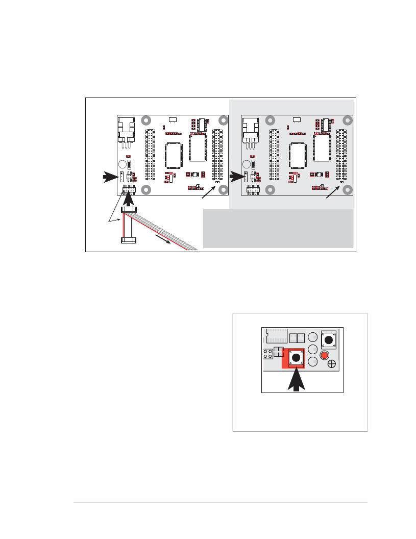
�3.3� Switching� Between� Program� Mode� and� Run� Mode�
�The� BL1810� is� automatically� in� Program� Mode� when� the� programming� cable� is� attached,�
�and� is� automatically� in� Run� Mode� when� no� programming� cable� is� attached.� See� Figure� 5.�
�Program� Mode�
�Run� Mode�
�U1�
�J4�
�U4�
�J5�
�U1�
�J4�
�U4�
�J5�
�J1�
�J2�
�GND�
�PA0�
�PA2�
�PA4�
�PA6�
�GND�
�PB0�
�PB2�
�PB4�
�PB6�
�WDO�
�GND�
�PE6�
�PE4�
�PE2�
�PE0�
�HV0�
�HV2�
�K�
�GND�
�VCC�
�PA1�
�PA3�
�PA5�
�PA7�
�GND�
�PB1�
�PB3�
�PB5�
�PB7�
�PCLK�
�PE7�
�PE5�
�PE3�
�PE1�
�GND�
�HV1�
�HV3�
�+RAW�
�VCC�
�U3�
�Rabbit� 2000�
�Y3�
�JP1�
�U5�
�SRAM�
�U6�
�RS-485�
�VCC�
�RXB�
�TXB�
�PC0�
�PC2�
�PC4�
�PC6�
�AD0�
�DA0�
�PD0�
�PD2�
�PD4�
�PD6�
�GND�
�485?�
�VCC�
�SM0�
�IOBEN�
�GND�
�/RST�
�GND�
�RXC�
�TXC�
�PC1�
�PC3�
�PC5�
�PC7�
�AGND�
�DA1�
�PD1�
�PD3�
�PD5�
�PD7�
�GND�
�485+�
�VCC�
�SM1�
�STAT�
�VBAT�
�GND�
�J3�
�JACKRABBIT� Z-World,� Inc.�
�RESET�
�J3�
�JACKRABBIT� Z-World,� Inc.�
�RESET�
�Colored� side�
�lines� up� with�
�pin� 1�
�PROG�
�DIAG�
�Programming�
�connector�
�To�
�PC� COM� port�
�Reset� pads� Reset� pads�
�RESET� BL1810� when� changing� mode:�
�Short� out� RESET� pads� below� header� J5,� OR�
�Press� RESET� button� (if� using� Prototyping� Board),� OR�
�Remove,� then� reapply� power�
�after� removing� or� attaching� programming� cable.�
�Figure� 5.� BL1810� Program� Mode� and� Run� Mode� Setup�
�3.3.1� Detailed� Instructions:� Changing� from� Program� Mode� to� Run� Mode�
�1.� Disconnect� the� programming� cable� from� header� J3� of� the� BL1810.�
�2.� Reset� the� BL1810.� You� may� do� this� as�
�explained� in� Figure� 5.� Figure� 6� shows� the�
�location� of� the� RESET� button� on� the� Proto-�
�typing� Board.�
�The� BL1810� is� now� ready� to� operate� in� the� Run�
�Mode.�
�3.3.2� Detailed� Instructions:� Changing�
�from� Run� Mode� to� Program� Mode�
�1.� Attach� the� programming� cable� to� header� J3�
�on� the� BL1810.�
�Figure� 6.� Location� of� Prototyping� Board�
�Reset� Button�
�2.� Reset� the� BL1810.� You� may� do� this� as� explained� in� Figure� 5.� Figure� 6� shows� the� loca-�
�tion� of� the� RESET� button� on� the� Prototyping� Board.�
�The� BL1810� is� now� ready� to� operate� in� the� Program� Mode.�
�Getting� Started� Manual�
�29�
�发布紧急采购,3分钟左右您将得到回复。
相关PDF资料
101-0523
KIT DEV RABBIT3000/RCM3000
101-1109
KIT EMBEDDED PLC APPLICATION
101-1147
KIT RIO PROGRAM I/O
101-606
CONN SOCKET IDC 60POS W/KEY GOLD
10113616-01531LF
CONN MOD JACK 8PORT 8/8 R/A PCB
10117863-5036010LF
CONN MOD JACK 8/8 R/A PCB
10118061-5005010LF
CONN MOD JACK 2PORT 8/8 R/A PCB
10118062-5001310LF
CONN MOD JACK 4PORT 8/8 R/A PCB
相关代理商/技术参数
101-0359-000
制造商:ITT Interconnect Solutions 功能描述:1010359000 / 101-0359-000 / Circular
10103592
制造商:FCI-CONNECTOR 制造商全称:FCI connector 功能描述:MICRO-USB B-TYPE REVERSE
10103592-0001LF
功能描述:USB接头 5P Quick Connect Micro USB TypeB Plug
RoHS:否 制造商:FCI 产品:USB Type A Connectors 标准:USB 3.0 端口数量: 位置/触点数量:9 型式:Female 电流额定值:1.8 A 安装风格:Through Hole 端接类型:Solder Pin 连接器类型:USB 3.0 Receptacle
10103593
制造商:FCI-CONNECTOR 制造商全称:FCI connector 功能描述:MICRO-USB B-TYPE MID-MOUNT
10103593-0001LF
功能描述:USB接头 5P Quick Connect Micro USB TypeB RCPT
RoHS:否 制造商:FCI 产品:USB Type A Connectors 标准:USB 3.0 端口数量: 位置/触点数量:9 型式:Female 电流额定值:1.8 A 安装风格:Through Hole 端接类型:Solder Pin 连接器类型:USB 3.0 Receptacle
10103593-0001LF
制造商:FCI 功能描述:MICRO USB B, RECEPTACLE, 5POS, SMT RT AN
10103594
制造商:FCI-CONNECTOR 制造商全称:FCI connector 功能描述:MICRO-USB B-TYPE RECEP.
10103594-0001LF
功能描述:USB接头 5P Quick Connect Micro USB TypeB Rcpt
RoHS:否 制造商:FCI 产品:USB Type A Connectors 标准:USB 3.0 端口数量: 位置/触点数量:9 型式:Female 电流额定值:1.8 A 安装风格:Through Hole 端接类型:Solder Pin 连接器类型:USB 3.0 Receptacle